Reel Makina, at its 10,000 m² facility in İzmir, manufactures slewing ring gears and bearings up to 5,000 mm using CNC technology. With our experienced operators, we ensure high-precision and high-quality production.
Frequently Asked Questions
A slewing ring is a machine component capable of carrying heavy loads and providing 360-degree rotational movement. It is used in equipment such as cranes, excavators, and wind turbines, and can withstand both radial and axial loads.

When selecting a bearing, factors such as load capacity, operating speed, environmental conditions, and ease of installation should be taken into account. In addition, it is important to choose the bearing type that meets the specific requirements of the application.
In the manufacturing of slewing rings, our company uses certified seamless rolled rings imported from Europe as raw materials. While C45 and 42CrMo4 materials are used as standard in our production, special materials can also be preferred depending on the application areas.
 |
||
|
|
||
  |
||
|
|
||
|
|
||
|
|
||
|
|
|
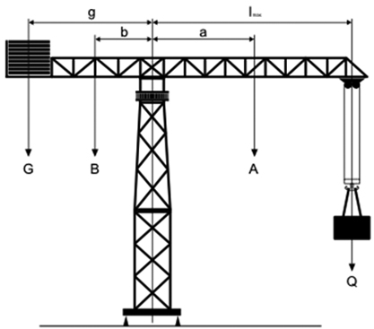
Fa: Axial Force (kN) Q: Load to be lifted (kN) |
Fa= Q + A + B + G
When 25% Test Load is Added:
When Wind Effect is Added: |
With the above formulas, you can easily calculate the axial forces and bending moments acting on the turntable gear. It is recommended that you use the maximum load and maximum distances in your calculations. If you wish, you can also include extra test loads or wind effects in your calculations.
|
 |
|
||
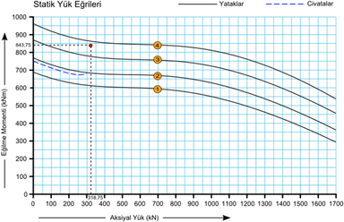
When we plot the results we obtained on a graph, we see that the ‘4’ numbered rotary table gear is suitable. |
SAFETY FACTOR(f):After performing load calculations, loads must be multiplied by a safety factor appropriate for the application area before selecting gears. |
||||||||||||||||||||||||||||
|
|
As shown in the figure, the black curve indicates the strength curve of the DTD bearings, and the blue dotted line indicates the strength curve of the bolts. The areas above these curves are not suitable for DTD selection. The coloured area is the area where the strength of the bearings and bolts is suitable. The intersection of the values obtained from your calculations must be within this |
There are certain points to consider during assembly in order to ensure a long service life of the slewing ring gear and bearing. First of all, the surfaces where the gear or bearing will be mounted must be cleanly machined and free from welding marks, burrs, paint, or other residues.
The flatness tolerances of the seating surface must not exceed the values given in Table 1. If these values are too high, the gear may either fail to rotate when the bolts are tightened or rotate with excessive friction.
|
BEARING DIAMETER |
SINGLE ROW BALL |
DOUBLE ROW BALL |
ROLLER-TYPE |
|
Up to 500 mm |
0.10 |
0.07 |
0.05 |
|
Up to 1000 mm |
0.12 |
0.10 |
0.07 |
|
Up to 1500 mm |
0.18 |
0.15 |
0.10 |
|
Up to 2000 mm |
0.22 |
0.18 |
0.12 |
|
Up to 2500 mm |
0.25 |
0.20 |
0.15 |
|
Up to 3000 mm |
0.27 |
0.25 |
0.17 |
Table 1: SEATING SURFACE TOLERANCES
After these two conditions are checked, the gear must be fastened with grade 10.9 bolts in accordance with DIN 267. The tightening sequence of the bolts should be as shown in Figure 1, and the specified bolt tightening torque values must be followed.
BOLT TIGHTENING SEQUENCE
During assembly, no filler materials, shims, or sheet-type materials should be placed between the gear and the seating surface. The "S" points marked on both rings of the gear indicate the start and end points of the hardening in the ball bearings. During assembly, these points must be positioned outside the main load-carrying areas.
Another factor affecting the service life of the slewing ring gear is lubrication. Before starting operation after installing the gear, the bearing housings must be properly lubricated. After the first 25 hours of operation, the bearings should be lubricated again, and periodic lubrication should be carried out every 100 hours. For gears with roller-type bearings, periodic lubrication is recommended every 50 hours.
Lubrication should continue until grease emerges from the dust seals in the grease fittings, and the same procedure must be applied to all grease fittings around the assembly. It should be noted that if the bearings remain without lubrication, friction and temperature will increase, causing wear on the bearings and making the gear unusable in a short time. Operators must be warned about this.
The appropriate lubricant should be selected based on the environment in which the slewing ring gear will operate, and care must be taken to prevent foreign substances such as dust, sand, water, or paint from entering the bearing housings.
If the machine has been idle for a long period, the bearings must be lubricated again before operation. Additionally, the tightness of the bolts should be checked every 3 months, and the condition of the dust seals should be inspected every 6 months. If the dust seals are torn or have lost their properties, they must be replaced with new ones.
The pinion gear and the slewing ring gear should be adjusted to operate at approximately 90° to the major load axis. During this process, the tooth profiles of the pinion and the slewing ring gear must be perfectly parallel to each other.
The operating backlash between the pinion gear and the slewing ring gear should be adjusted as shown in Figure 1, to a value of Module × 0.035. If multiple pinions are used, this adjustment must be repeated for each pinion.
These adjustments must be made at the points marked with blue paint on the teeth of the slewing ring gear.
After completing all adjustments and tests, and ensuring that the axes of the pinion and slewing ring gear are aligned, the operating backlash is correct, and the contact surfaces of the teeth are parallel, lubricate the teeth. For more detailed information on lubrication, refer to the "Lubrication and Maintenance" section.
Standard slewing ring gears, after manufacturing, are first wrapped in VCI corrosion-preventive paper and then in nylon. If the products are to be stored for a long period, corrosion-preventive oil such as Tectyl should be applied to all surfaces before packaging. In this way, the slewing ring gears secured on pallets are ready for shipment.
There are important precautions to take during the transportation and storage of slewing ring gears. They must never be transported or stored in a vertical position, and vertical impacts should be avoided.
Products should be kept indoors in a dust-free and dry environment. The humidity should not exceed 60%, and the temperature should be between 15–35°C. They must not be exposed to direct sunlight. The storage surface should be solid, and there should be no risk of mechanical vibration or impacts. Equal-sized spacer layers should be placed between products, and no more than three units should be stacked on top of each other.
Transportation must be carried out using the lifting holes or mounting holes on the slewing ring gear. If multiple slewing ring gears are secured on a pallet, they should be moved using a forklift or pallet truck.
Standard slewing ring gears are specially designed for use in mobile cranes, tower cranes, telescopic boom cranes, excavators, concrete batching plants, concrete pumps, robots, radars, the defense industry, offshore platforms, bottling and filling plants, custom-designed industrial machines—in other words, anywhere rotational motion is required.
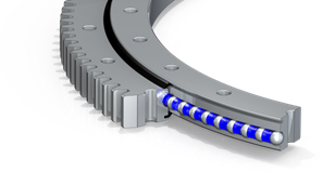
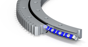
Components of a Slewing Ring Gear
The designed gear components are manufactured from various materials and assembled to form the slewing ring gear.
- Outer Ring
- Inner Ring
- Mounting Holes
- Plug
- Seal
- Gear Teeth
- Balls
- Grease Fittings
Regular maintenance, proper lubrication, correct assembly, and operation within specified conditions extend the service life of slewing ring gears and bearings. Additionally, avoiding excessive loads and following the manufacturer’s instructions are also important.
You can download the technical drawings and 3D models of our products from the relevant product pages on our website or request them by contacting us directly.
Yes, we manufacture bearings and gears designed according to our customers’ specific requirements. When you provide us with your project’s specifications, we work to offer the most suitable solution.
Our products are manufactured in accordance with international quality standards and hold ISO 9001 and other relevant certifications. For detailed information and copies of the certificates, you can contact us directly.
Your orders are prepared as quickly as possible, depending on product availability and production time, and delivered safely. For more detailed information, you can contact our sales team.